DISTRIBUTOR-FIRST SUPPLY PARTNER · SINCE 1999 Live · Compressed Air System

SPC Company
Compressed Air / Monitoring / Pressure Sensing / Pressure Sensor
Layer 07 · Monitoring Price · Adsens
What it is

Pressure Sensor

Compare tiers ↓

A pressure sensor reads what pressure a compressed air system is holding at a given point, or checks the differential pressure (the difference in pressure between upstream and downstream of a filter, used to indicate when an element is loading up and due for change) across a filter. It sits in the monitoring layer as the simplest of its instruments, the entry-tier product that answers a status question (is the system at setpoint, is a filter loaded, has the compressor cut out) rather than producing the audit-grade precision a logged historian needs. Two install patterns: single-point reading off the line (one tap), or differential check across a filter (two taps, one each side). Output is either a visual gauge an operator reads by eye, or an electrical signal (4-20 mA, Modbus, or IO-Link) to a controller.
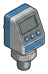
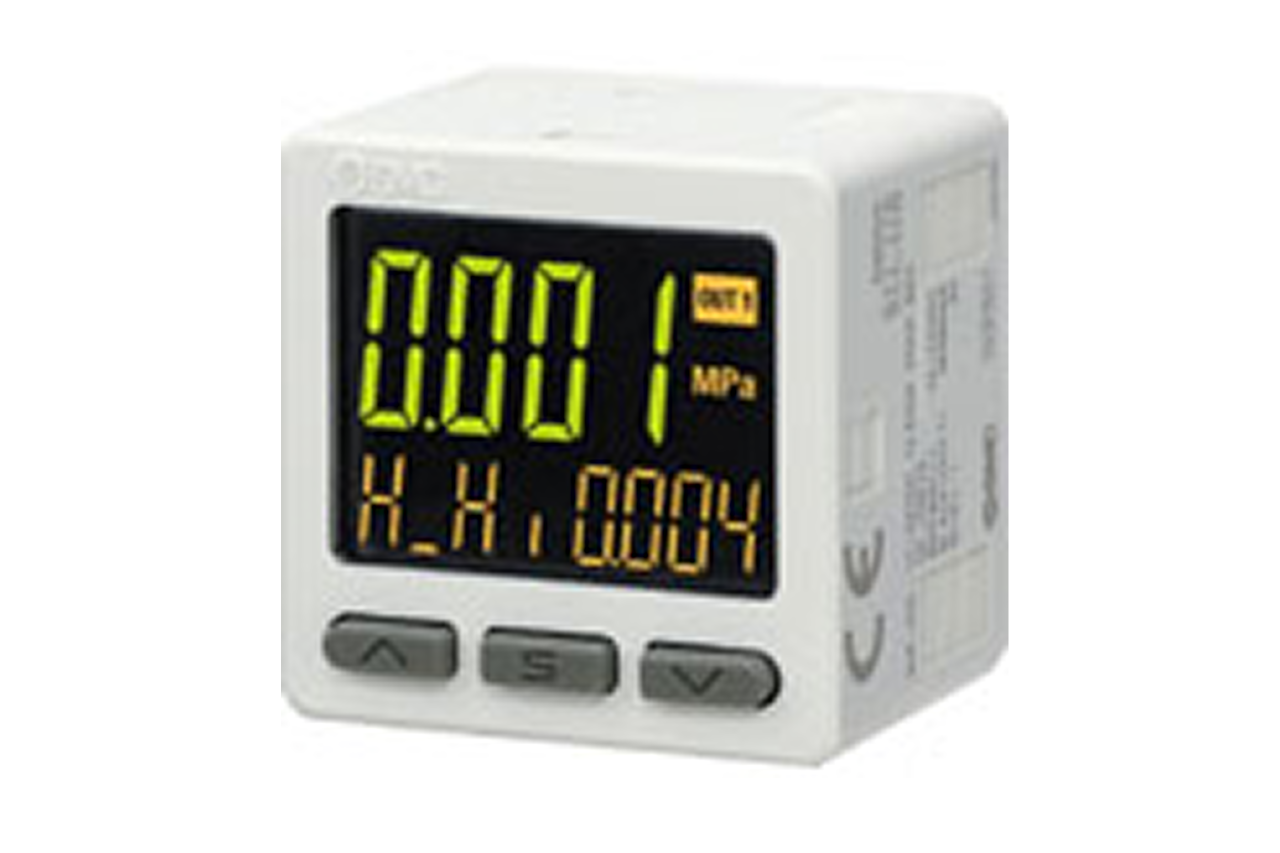
Pictorial Representative pressure sensor
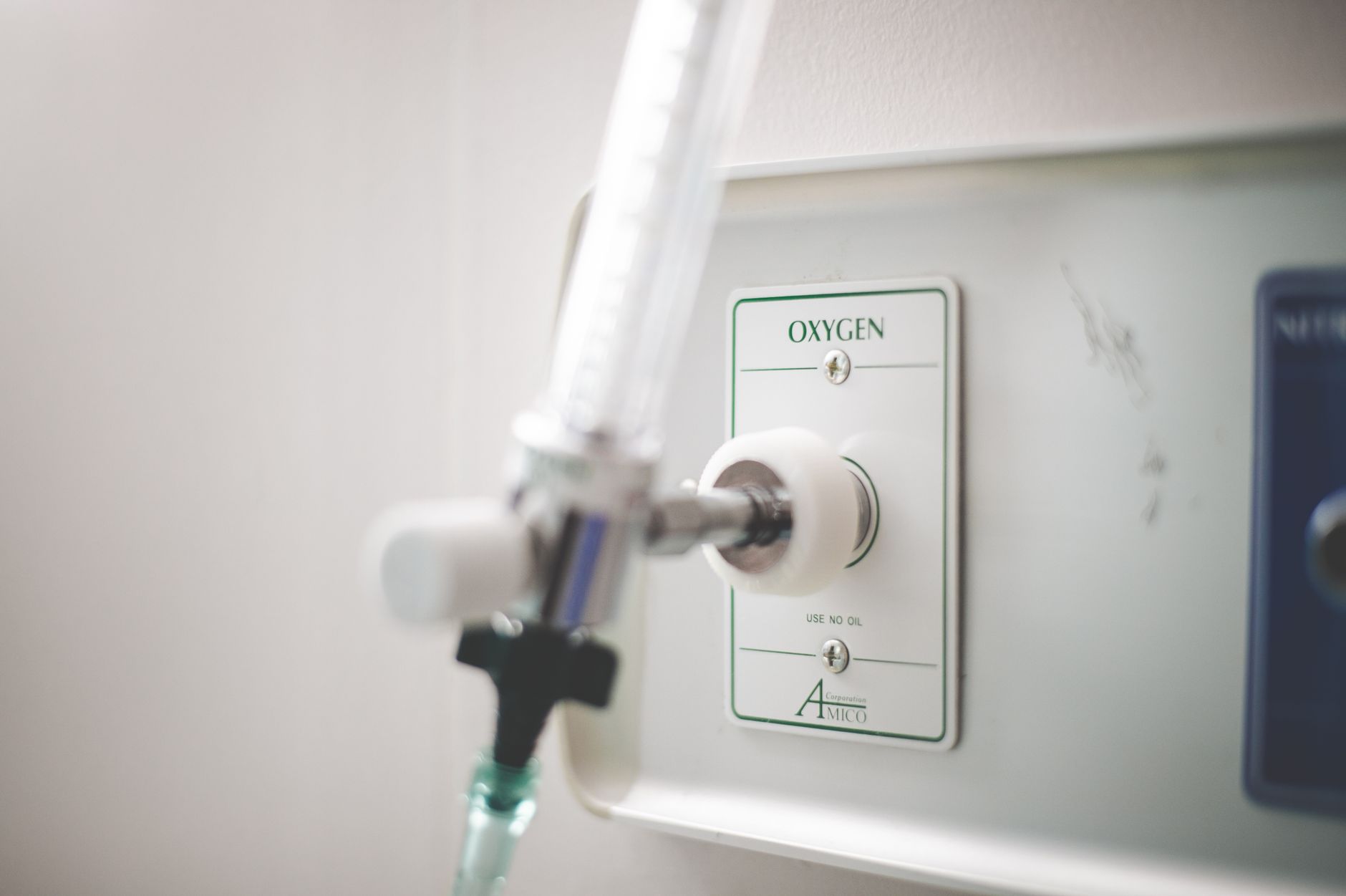
Pressure Sensor — representative illustration
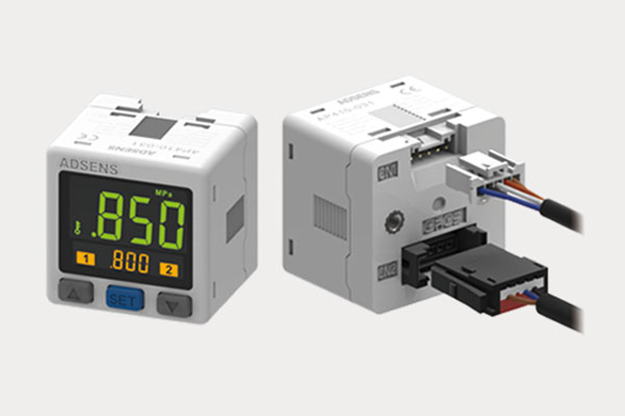
Real-world reference Representative pressure sensor
Pressure Sensor — representative product photo
Why it's needed

Why this matters.

When a pressure sensor is the right call, and when to spec something else. Review the points below.

01 · Key point
Filter differential pays fastest.

Every PSI of avoidable drop across a loaded filter is ~0.5% of plant electricity. A pair of sensors across each coalescing stage (alarm at 8-10 PSI) recovers element cost in months, every multi-filter plant.

02 · Key point
Accuracy matches the job.

±1% of range for compressor-discharge control. ±0.5 PSI absolute for filter-differential alarms. ±0.25% with cal certificate for audit-grade. Match spec to job, over-spec wastes budget, under-spec produces wrong decisions.

03 · Key point
Integration scales the install.

4-20 mA for simple analog. Modbus-RTU for plant historians. IO-Link for modern PLCs, single cable, native config, calibration data carried in the protocol. The output type determines wiring, cost, and what the customer can do with the reading.

04 · Pro tip
Rate the sensor for the spike.

Confirm system working pressure AND maximum spike pressure within sensor range with 1.5x safety margin. Add a capillary snubber on reciprocating-compressor lines, pulsation fatigue is the leading cause of premature failure.

05 · Where not to use
Mechanical gauge feeding control logic.

Cheap analog gauges drift, fail without warning, and can't be wired to a controller. → Re-spec to electronic sensor with documented calibration for any reading driving alarms, control, or maintenance decisions.

06 · Where not to use
Economy sensor in temperature-varying space.

Cheaper sensors have weak temperature compensation, readings drift seasonally with no real system change. → Use sensors with documented temperature coefficient for outdoor, unheated, or audited installs.

07 · Where not to use
Audit-grade compressed-air purity work.

Generic pressure sensors don't carry the calibration documentation an FDA, GFSI, or USP auditor will ask for. → Re-spec to ISO 8573-1 analyzer sensors for any pharma, food-contact, or medical breathing-air install.

Key selection criteria

What we need to spec it right.

From the machine spec sheet to the part number. Answer what you know, leave the rest blank, and send.

04Choose your priority  ·  core differentiator

Whatever your lever — performance, value, or price — SPC has the right brand.

Pick the priority; the quote desk handles the cross-reference.

03 Price 1 brand
Where it's used

Industries served.

Each industry below uses this product across the listed areas. Open an industry to see how it fits the rest of its system.

Also applies to Compressor discharge monitoring · The single most universal install point for a pressure sensor · System header and demand-side monitoring · Filter differential monitoring (coalescing, particulate, activated carbon) · Dryer differential and outlet monitoring · Compressor sequencer and multi-machine load-sharing systems · Sensor count grows with machine count · Receiver tank and storage volume monitoring · Vacuum-side applications

Install · 6 critical steps

The things that matter on the first install.

Step 01
Pick install locations operators will actually read
Sensors are most valuable when they are readable, a sensor behind a panel in a mechanical room does not get read. Put the gauge or display in the operator's walking path, or wire the reading to a control-room display. The sensor's value is operator behavior, not the sensor itself.
Step 02
Verify pressure rating, port spec, and wetted-parts material
Confirm system working pressure AND maximum spike pressure are within the sensor's rated range with 1.5x safety margin. Confirm port thread (NPT / BSP / metric) and size. Confirm wetted-parts material is compatible, most compressed air is stainless or brass, but oil-bearing lines may require different metallurgy.
Step 03
Install an isolation valve and a snubber for high-pulsation lines
Every electronic sensor benefits from an isolation valve between sensor and main line, lets the sensor be removed for calibration or replacement without depressurizing. For installs near reciprocating compressors or fast-cycling valves, add a capillary snubber or piston-type pulsation dampener: pulsation fatigue is a leading cause of premature sensor failure.
Step 04
Wire the output per the sensor's wire-configuration spec
4-20 mA sensors come as 2-wire (loop-powered) or 3-wire (separate power and signal); confirm which the sensor and PLC input card require. IO-Link sensors take a single 4-conductor cable to the IO-Link master. For local gauge readout, confirm scale and orientation for operator visibility.
Step 05
Configure scaling at the PLC, controller, or display
The sensor's 4-20 mA output maps to its full range; a 0-200 PSI sensor reads 4 mA at 0 PSI and 20 mA at 200 PSI. The PLC scaling must match the sensor's range; mismatched scaling is the most common cause of readings that look wrong but are actually correct sensors with bad math at the controller. IO-Link and Modbus carry scaling in the protocol, typically correct out of the box.
Step 06
Set alarm setpoints and document the handoff
For filter-differential: set the alarm at the manufacturer's recommended change-out differential (typically 8-10 PSI for coalescing). For compressor-discharge: set low-pressure alarms below cut-in setpoint so a failed compressor produces an alarm rather than silent demand. Document setpoints, readback cadence, and response procedure as part of the install handoff.
Troubleshoot · top failures

Most returns trace to one of these causes.

Symptom
Most likely cause
Fix
Sensor reading is stable but doesn't match a reference gauge at the same point.
Sensor range/scaling mismatch at the PLC, sensor past calibration interval drifting, reference gauge itself out of calibration (often the bigger problem, analog gauges drift more than electronic sensors), or sensor and reference are not measuring at exactly the same point.
Verify scaling at both ends. Compare both readings against a traceable calibrated reference. If the electronic sensor is correct and the wall gauge is wrong, replace the wall gauge, do not adjust the electronic sensor to match an uncalibrated reference.
Reading oscillates rapidly even though system pressure appears stable.
Pressure pulsation from reciprocating compressor or rapid-cycling valve coupling into the sensor, install location too close to a control valve, electrical noise on the 4-20 mA loop from nearby VFD (Variable Frequency Drive), or sensor's response time too fast for the application.
Install a snubber or pulsation dampener at the sensor. Move the sensor to a more stable point if practical. For 4-20 mA loops, verify cable shielding and route away from power runs. Configure damping at the PLC if the underlying pulsation cannot be removed.
Sensor reads pegged at zero or pegged at full scale.
Mechanical failure of the sensing element (pressure-spike damage or fatigue), wiring open or shorted, power supply failed, or for 4-20 mA loops the loop is broken (open circuit reads 0 mA = below-range or fault).
Verify loop continuity with a multimeter. Verify power supply voltage. If wiring and power are healthy, the sensor is failed, replace. Investigate whether a recent event (water hammer, compressor unload spike, hydrostatic test) damaged the sensor and add a snubber for the replacement.
Filter-differential reading climbs faster than expected after a fresh element install.
Wrong element installed (incorrect size or grade), bypass valve left open during the install, upstream contamination dump from disturbed piping during service, or the previous element was masking a downstream restriction.
Verify element part number against the housing spec. Confirm bypass valve is closed. Inspect downstream piping. If differential is rising at expected rate but starting from an elevated baseline, the install is fine; the new baseline is the new reading.
4-20 mA reading at the PLC drifts seasonally with no apparent system change.
Sensor sensitive to ambient temperature (cheaper sensors have less temperature compensation), wiring runs through an outdoor or unheated space causing seasonal connection-resistance change, or PLC input card drifting.
Check sensor's temperature-coefficient spec, if the application requires temperature stability, the sensor may be underspecified. Inspect wiring for outdoor or condensation exposure. For audited installs, use sensors with documented temperature compensation rather than economy-tier sensors in temperature-varying environments.
IO-Link sensor not appearing on the network.
Sensor wired to wrong master port, IO-Link master not configured for the sensor's vendor ID, cable not rated for IO-Link, or sensor in legacy SIO mode rather than IO-Link mode.
Verify port assignment at the master. Update the master's device configuration with the sensor's IODD (IO Device Description) file. Use IO-Link-rated cable. Reset sensor to IO-Link mode. Most IO-Link first-install issues are configuration on the master side rather than sensor problems.

Get the right pressure sensor on quote in 24 hours.

Send us the application — a specialist routes you to the correct tier with a configured part. Lead-times and pricing returned within one business day.

Open quote engine ↑