DISTRIBUTOR-FIRST SUPPLY PARTNER · SINCE 1999 Live · Compressed Air System

SPC Company
Compressed Air / Monitoring / Flow & Demand / Thermal Mass Flow Meter
Layer 07 · Monitoring Value · BEKO
What it is

Thermal Mass Flow Meter

Compare tiers ↓

A thermal mass flow meter measures how much compressed air a plant actually consumes, in SCFM (Standard Cubic Feet per Minute, flow corrected to a reference temperature and pressure so two readings can be compared). It is the foundational audit instrument that answers "do you know how much air your plant uses?" Installed on the main header downstream of the dryer, it sits in the monitoring layer; it adds no treatment or capacity, only reports what the system is doing. Two install styles: inline (built-in measuring section, plumbed into smaller pipe) and insertion-probe (single tapped fitting, serves large headers, hot-tap installable into a live line with no plant shutdown).
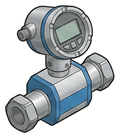
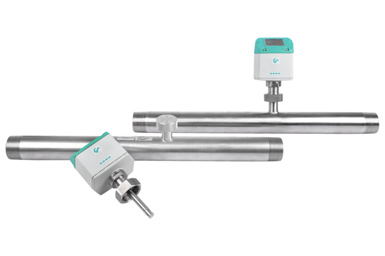
Pictorial Representative thermal mass flow meter
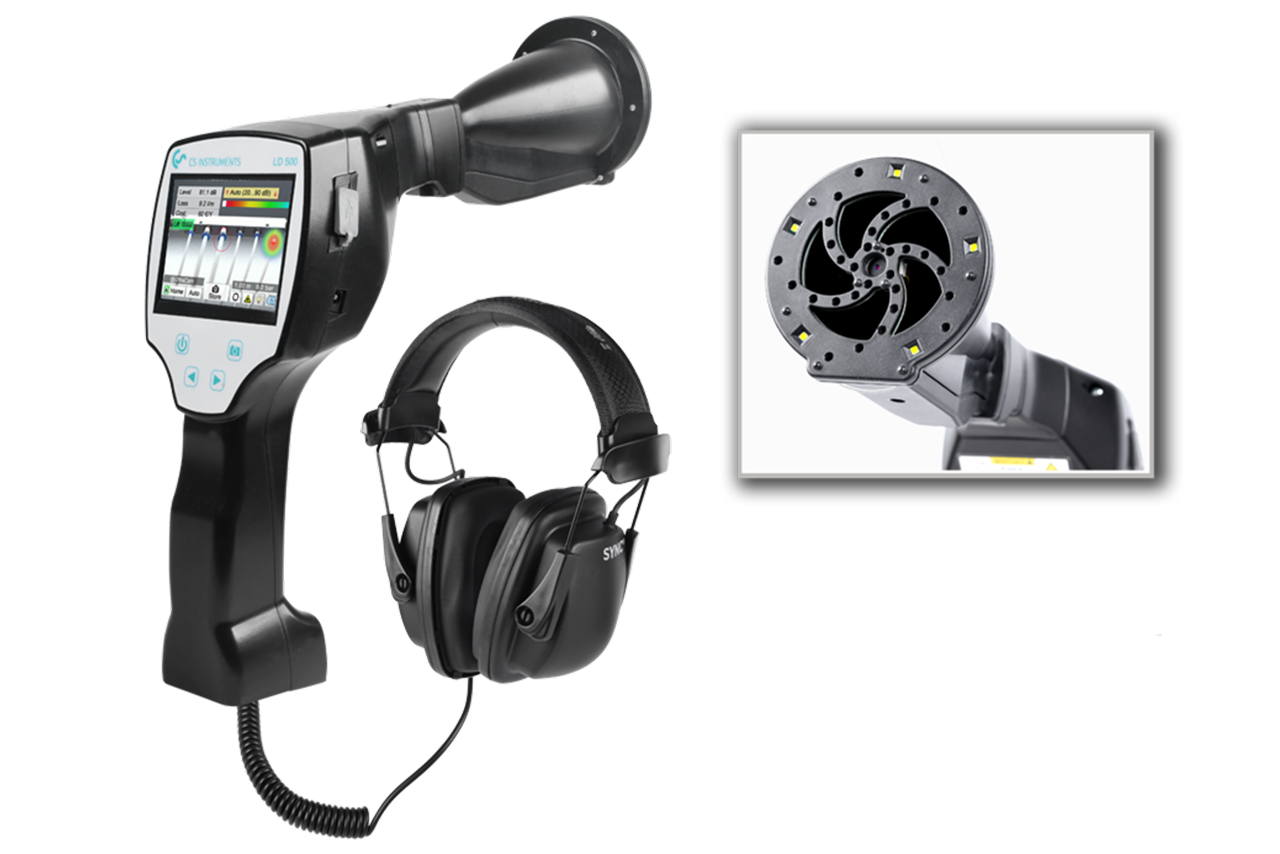
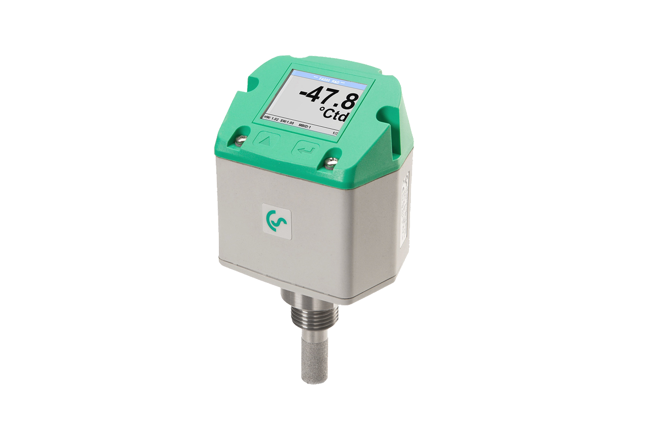
Thermal Mass Flow Meter — representative illustration
Real-world reference Representative thermal mass flow meter
Thermal Mass Flow Meter — representative product photo
Why it's needed

Why this matters.

When a thermal mass flow meter is the right call, and when to spec something else. Review the points below.

01 · Key point
It reads true mass flow.

Calorimetric sensing reports SCFM directly: no separate pressure/temperature correction. Typical accuracy ±1 to ±1.5% of reading: audit-grade for sizing, chargeback, and leak verification.

02 · Key point
Hot-tap installs live.

Insertion-probe goes in through a full-port isolation valve on a pressurized header, no plant shutdown. Avoids shutdown during installation on a continuous-duty plant.

03 · Key point
It pays for itself on sizing.

Plants without flow data routinely buy 30-60% more compressor than they need. A two-week datalog before a 50+ HP quote saves more than the meter costs, every time.

04 · Pro tip
Match install style to pipe.

Inline for smaller pipe and new construction, built-in measuring section. Insertion-probe for large headers and any live install, probe length must match pipe ID exactly.

05 · Where not to use
Wide-turndown single-meter installs.

Thermal sensors have a minimum-flow floor, below it, sensor cannot distinguish flow from no-flow. → Re-spec to a second smaller meter for off-shift bands over 100:1 turndown.

06 · Where not to use
Wet or oil-contaminated air.

Water slugs and oil aerosol contaminate the heated element, readings drift, sensor fails early. → Verify upstream coalescing filter and dryer before install; rapid drift = failed filtration.

07 · Where not to use
Close to elbows, valves, reducers.

Swirl distorts the velocity profile and biases the reading. → Hold 15-20 pipe diameters straight upstream, 5 downstream: anything less and the meter reads turbulence, not flow.

Key selection criteria

What we need to spec it right.

From the machine spec sheet to the part number. Answer what you know, leave the rest blank, and send.

04Choose your priority  ·  core differentiator

Whatever your lever — performance, value, or price — SPC has the right brand.

Pick the priority; the quote desk handles the cross-reference.

02 Value 2 brands
Where it's used

Industries served.

Each industry below uses this product across the listed areas. Open an industry to see how it fits the rest of its system.

Also applies to Compressed-air energy audit baseline (every plant) · Department-level chargeback in multi-department plants · Compressor sizing for new installs and replacements · the meter pays for itself on the sizing decision alone · Leak-survey verification (before-and-after) · Continuous monitoring in critical-process plants · VFD compressor optimization · Branch-line capacity studies for plant expansion

Install · 6 critical steps

The things that matter on the first install.

Step 01
Confirm install style and pipe geometry
Pull pipe nominal diameter, OD/ID, schedule, and material at the install point. Inline for smaller pipe and new construction; insertion-probe for larger headers and any live install. Order probe length matched to pipe ID, wrong length is the most common pre-install error.
Step 02
Pick a straight-pipe run for the install location
Thermal meters need undisturbed flow at the sensor: 15-20 pipe diameters of straight pipe upstream, 5 diameters downstream. Avoid elbows, valves, tees, and regulators immediately upstream, swirl distorts the velocity profile and biases the reading.
Step 03
For insertion installs, hot-tap the line
Install a full-port isolation ball valve at the tapping fitting first. Drill through the valve, then insert the probe; the valve isolates the line during probe entry. Slide the probe through the gland to centerline (or OEM's specified offset), confirm the flow-direction arrow on the probe head aligns with actual flow, torque the gland fitting.
Step 04
For inline installs, depressurize, cut, and re-pipe
Lock out the line. Cut to the meter's face-to-face dimension, install per the OEM's flange or threaded-end spec, confirm the flow arrow matches actual flow, reversing an inline thermal meter ruins the calibration. Pressurize, leak-check, energize.
Step 05
Wire output to display or PLC/SCADA
For 4-20 mA (Programmable Logic Controller analog input): two-wire loop-powered, scale at the receiving end to the meter's configured SCFM range. For Modbus-RTU (RS-485 serial bus): daisy-chain with 120Ω termination at both ends, unique slave address per meter. For Ethernet/PoE: configure the IP and SCADA tag.
Step 06
Zero-check and document
With the line pressurized and no flow (compressor off), the meter should read at or near zero. Any significant non-zero reading at no-flow means wrong orientation, mis-set config, or calibration issue. Log meter serial, pipe size, probe length, configured units, full-scale range, output config, and SCADA tag. Schedule annual calibration verification.
Troubleshoot · top failures

Most returns trace to one of these causes.

Symptom
Most likely cause
Fix
Meter reads lower than the compressor nameplate suggests.
The meter is reading correctly and the plant's actual demand is well below nameplate (normal, compressors are oversized 30-60% on average). Alternative: probe inserted at wrong depth (sensor in boundary layer, not centerline), or wrong pipe diameter configured.
Do not assume the meter is wrong. Verify probe depth against OEM spec and configured pipe ID against actual ID. If both correct, the reading is reality.
Erratic large swings with steady demand.
Turbulent/swirling flow at the sensor (meter too close to elbow, valve, or reducer), water slugging through a wet header from a failing dryer, or electrical noise on the 4-20 mA cable picking up VFD (Variable Frequency Drive) harmonics.
Confirm 15-20 pipe diameters of straight pipe upstream. Verify air at the meter is dry. Route signal cable away from VFD power lines; use shielded cable grounded at one end only.
Reads zero with confirmed flow.
Probe inserted backwards (sensor pointing downstream), wrong flow-direction in config, sensor element failed, or 4-20 mA loop wiring open/reversed.
Verify probe arrow aligns with pipe flow. Check meter config. Measure loop current and compare to local readout. If wiring and config are correct, the sensor element has failed, return to OEM.
Drift over time at the same operating condition.
Sensor contamination from oil aerosol, dust, or condensate (most common in plants with degraded filtration or a failed dryer); long-term sensor aging.
Verify upstream coalescing filter and dryer are working. Schedule annual calibration verification; thermal meters drift slowly and re-calibrate every 1-3 years. Rapid drift (months) = failed upstream filtration; clean or replace the sensor per OEM procedure.
Reads correctly daytime, erratic or zero off-shift.
Thermal meters have a minimum-flow sensitivity; below a certain velocity the sensor cannot distinguish flow from no-flow. Off-shift demand drops below the meter's usable range.
Check configured range against actual off-shift flow. Either accept noisy off-shift readings, or, for very wide demand turndown, install a second smaller meter sized for the lower band. Single-meter solutions over 100:1 turndown are not realistic with thermal technology.

Get the right thermal mass flow meter on quote in 24 hours.

Send us the application — a specialist routes you to the correct tier with a configured part. Lead-times and pricing returned within one business day.

Open quote engine ↑